rvrtrash
Well-known member
- Joined
- Apr 25, 2003
- Messages
- 3,667
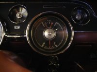
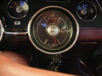
Quite some time ago I promised to give feedback on a conversion from the barely usable factory ammeter to a voltmeter by Rocketman's Classic Cougar. They utilize a factory gauge face (thank you brother Rob for the core) so it looks "factory". For various reasons, I'm just now getting around to installing it and thought I'd do a "how-to" while I was at it. Of course I decided this after starting, so will skip the mechanics of removing the cluster and replacing the gauge. Those steps are fairly straight forward anyway, so I'll concentrate on wiring it in. The new voltmeter requires a ground and switched 12V power source, as opposed to the constant on two positives of the ammeter. The first picture shows the difference in the gauges (voltmeter in cluster) in the static condition. Note the position of the needles, although the ammeter would normally be pointing straight down, not up, like in the picture.
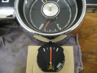
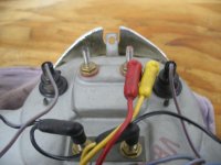
The second picture shows the back of the cluster. The red wire goes on the left side, as noted on the housing, but if you look close, the new gauge has the positive on the right side, indicated by a red dot on the stud end. I like leaving things as original as possible, so will use the factory wiring, in the original position and make my changes elsewhere.
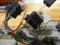
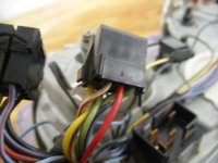
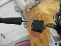
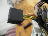
The original cluster goes to the two unswitched "hots" in an 8 pin plug. Since I can't use two hots, I'll move the factory wires to two vacant spots, using a pin extractor. Pics 3, 4, 5 and 6 show moving the wires to the new locations, in same orientation as original.
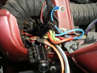
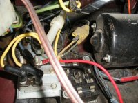
There is a 12V switched source available in a yellow plug just above the fuse box (pic 7) that is convenient. Ford uses some odd sizes, so I used a standard male bullet connector and spread the terminal out a little so it would fit tight, with a small screwdriver, while holding it with pliers. If you're not careful, this is an easy way to check your blood's ability to clot. After modifying the terminal and crimping it on to an 18 Gauge wire, I inserted it in to the plug (pic 8).
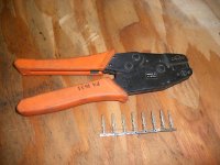
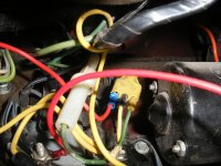
Next, run the new power wire up to the harness plug that connects to the cluster plug you previously moved the wires in. The power (red) wire will go in to the plug, using some male pins that you can get at Radio Shack. Pictured are the pins and the correct crimp tool (pic 9). Remember the supply side of the new gauge being on the yellow wire side? I like using red for power, so this is where we'll make the change, although if I was to do it again, I'd use yellow for power instead of red, to reduce confusion. Insert the power (red) wire into the plug opposite where the yellow wire is in the cluster plug. Run a ground wire (I used blue in this installation but black is normally the ground) in to the space opposite the red wire in the cluster plug. The other end of the blue (ground) wire will go to the factory ground location on the support behind the cluster (pic 10).
At this point you would test your connections and gauge prior to complete installation of the cluster. Make sure you don't have any bare terminals on the back of the cluster touching metal before you hook the battery back up. When you know everything works, unhook the battery and complete the gauge cluster installation. The next post will be of the gauge "in action".
Steve
The second picture shows the back of the cluster. The red wire goes on the left side, as noted on the housing, but if you look close, the new gauge has the positive on the right side, indicated by a red dot on the stud end. I like leaving things as original as possible, so will use the factory wiring, in the original position and make my changes elsewhere.
The original cluster goes to the two unswitched "hots" in an 8 pin plug. Since I can't use two hots, I'll move the factory wires to two vacant spots, using a pin extractor. Pics 3, 4, 5 and 6 show moving the wires to the new locations, in same orientation as original.
There is a 12V switched source available in a yellow plug just above the fuse box (pic 7) that is convenient. Ford uses some odd sizes, so I used a standard male bullet connector and spread the terminal out a little so it would fit tight, with a small screwdriver, while holding it with pliers. If you're not careful, this is an easy way to check your blood's ability to clot. After modifying the terminal and crimping it on to an 18 Gauge wire, I inserted it in to the plug (pic 8).
Next, run the new power wire up to the harness plug that connects to the cluster plug you previously moved the wires in. The power (red) wire will go in to the plug, using some male pins that you can get at Radio Shack. Pictured are the pins and the correct crimp tool (pic 9). Remember the supply side of the new gauge being on the yellow wire side? I like using red for power, so this is where we'll make the change, although if I was to do it again, I'd use yellow for power instead of red, to reduce confusion. Insert the power (red) wire into the plug opposite where the yellow wire is in the cluster plug. Run a ground wire (I used blue in this installation but black is normally the ground) in to the space opposite the red wire in the cluster plug. The other end of the blue (ground) wire will go to the factory ground location on the support behind the cluster (pic 10).
At this point you would test your connections and gauge prior to complete installation of the cluster. Make sure you don't have any bare terminals on the back of the cluster touching metal before you hook the battery back up. When you know everything works, unhook the battery and complete the gauge cluster installation. The next post will be of the gauge "in action".
Steve
Attachments
Last edited: