• Welcome to the CaliforniaSpecial.com forums! - You are currently viewing the forums as a GUEST. To take advantage of all our site features, please take a moment to join our community! It's fast, simple and absolutely free.

    If you have problems registering or can't log into your account, please contact Admin.

    Please Note: If you are an existing member and your password no longer works, click here to reset it.

1968 %&#@$ Ammeter/Circuit

franklinair

Well-known member
Joined
Mar 1, 2007
Messages
4,744
I feel like I'm flogging a dead horse:
The ammeter reads continuity with an Ohm meter, barely deflecting the needle. (about the needle width)
The 2 wire circuit, one lead to the + post on the solenoid, one lead going to the Alternator reads 1.25 Ohms.
With power on (Battery only) I turned on the headlights expecting to see the Ammeter needle deflect negative. Nada, barely discernable.
I hate having to resign myself to having a non functional Ammeter.

Neil:mad:
 

stangfan

Well-known member
Joined
Jun 12, 2012
Messages
1,890
Location
Victoria BC Canada
My understanding is that the ammeters are so old that they rarely register much of a change in current. The one in my GT/CS seems to pop up above the vertical centre line when the engine is running, but not by much.
 

whodat

Well-known member
Joined
Mar 26, 2010
Messages
668
I had mine converted to a volt gauge. When I put everything back together it didn't work. I still haven't removed the cluster to see what the problem is because it's such a pain in the butt to do.
 
OP
OP
franklinair

franklinair

Well-known member
Joined
Mar 1, 2007
Messages
4,744
I did a continuity check on both wires (power off/Battery was disconnected). I checked this circuit from the Red & Yellow wires at the Instrument Cluster connector and read 1.25 Ohms after having cleaned all connections. In essence, you're reading a loop due to the fact that BOTH wires (Red & Yellow) terminate on the same terminal on the Starter Solenoid due to a spliced wire in the engine compartment harness.
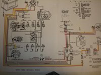
The wiring diagram shows the Red wire going from the Ammeter to the +(Battery) terminal on the Starter Solenoid. The Yellow wire goes from the Ammeter to a Splice in the engine compartment which branches to the Alternator AND the very same terminal on the Starter Solenoid as the Red wire, effectively making them the Same point electrically.
I'm sure Ford's theory was just to look at the direction of current flow between the Battery & Alternator, but in order for it to work you'd have to have a VERY sensitive coil in the Ammeter- which these cars obviously don't have.

Neil
 

CougarCJ

Well-known member
Joined
Jul 17, 2006
Messages
2,216
My electrical guys here at work both say that to properly test these ammeters, you would have to have a battery and something to act as a draw, with the ammeter between them. This will only test the negative side of the ammeter though. They think that the little coil creates a magnetic field that moves the needle. Please let me know if this is incorrect?
 
OP
OP
franklinair

franklinair

Well-known member
Joined
Mar 1, 2007
Messages
4,744
The problem as I see it, is such a minute current differential and an insensitive meter movement, the system as designed is doomed to mediocrity at best. I did order a new ammeter from CJ Pony Parts, but I'm not holding any high expectations. I do have an idea as far as modifying the circuit, and I'll keep everyone posted.

Neil
 
OP
OP
franklinair

franklinair

Well-known member
Joined
Mar 1, 2007
Messages
4,744
Did some further checking (while I wait for the new ammeter).
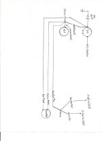
The two wires (Red#655 & Yellow#654) that go from the ammeter to the + side of the starter solenoid read different resistance. The Red wire read 1.5 Ohms from end to end, and the Yellow wire read .25 Ohms. They both appear to be 18 gage, equal length. These readings were from the Instr cluster connector to the Solenoid. The only thing I can think of for the resistance differential is the fact that the Yellow wire has a factory splice that branches off to the Alternator (Green/White#3).
I have the Mustang wiring diagram, and made a simplified drawing (for my simple mind).
Steve seems to understand this circuit, but I don't.:confused: To me, if the 2wires are connected together at the solenoid (same electrical potential) I cannot grasp how the Ammeter would sense a + or - current flow direction. Unless the Ammeter functions as the old style 'induction' type that senses direction of current flow, but they had a 'loop' that sensed the current flow direction, rather than the 2 posts on the Mustang Ammeter.

Neil
 

Attachments

  • Schematic.jpg
    Schematic.jpg
    102.3 KB · Views: 38
  • Ammeter Circuit.jpg
    Ammeter Circuit.jpg
    34.9 KB · Views: 37

rvrtrash

Well-known member
Joined
Apr 25, 2003
Messages
3,665
Neil, both wires should have the same resistance for the ammeter to even have a chance to work, and the lower it is, the better. Wires, and the connections, build up corrosion after time that increases resistance. All wiring has resistance in it. The longer the length and the smaller the wire diameter, the greater the resistance. The Ford ammeter circuit uses that wire resistance between the two connection points to cause a small amount of parallel current to flow though the ammeter, in whichever direction the current is flowing (charge or discharge). The closer the ammeter circuit resistance is to the resistance of the main harness wire between the two points, the better it will work. Unfortunately I think it was a case of one engineer not talking to another, because even when new, the circuit didn't work very well, and only got worse with time. At one point I toyed with the idea of moving the wire spliced in to the main harness a few feet further down the harness to increase the resistance between the points, but finally decided to just get a voltmeter from RCC instead. Ammeters are a holdover from the days when cars had generators, because generators produce varying levels of amps, speaking simply. Alternators should have voltmeters, because alternators produce varying levels of voltage. Hope this helps some.

Steve
 
OP
OP
franklinair

franklinair

Well-known member
Joined
Mar 1, 2007
Messages
4,744
After much frustration, poor engineering on Ford's ammeter circuit design, and Steve's input I have decided to convert the electrical indication to a Voltmeter configuration. I've communicated with Rob McMullen of RCC Innovations and ordered a Voltmeter for my CS. Simple wiring mod, and it will be done. When I get it completed,I'll be glad to share the info. (I'm also going to install his Minitach in place of the clock.)

Neil
 
Top