• Welcome to the CaliforniaSpecial.com forums! - You are currently viewing the forums as a GUEST. To take advantage of all our site features, please take a moment to join our community! It's fast, simple and absolutely free.

    If you have problems registering or can't log into your account, please contact Admin.

    Please Note: If you are an existing member and your password no longer works, click here to reset it.

1968 Starting Issue

OP
OP
Mosesatm

Mosesatm

Well-known member
Joined
Jan 18, 2005
Messages
9,178
Since you've replaced all the usual suspects, here's a simple fix:
Simply run a jumper wire from the solenoid (small terminal, brown wire) to the + terminal of the coil. It will furnish 12V to the coil when the Ign switch is in the Run position.

This way toy have the best of both worlds: 12V to the coil in the Start mode, and 12V to the coil in the Run mode. (Pertronix coils love 12V)

Neil

Neil,
I tried that. Didn't work. The only way the car will start every time is to completely bypass the factory wiring.
 

p51

Well-known member
Joined
Aug 2, 2005
Messages
1,025
Location
NorCal
I agree the low voltage is probably the issue, but why is the voltage so low? I still think someone may have switched the resistor wire and the 12V wire.

OK, here's a possible theory of failure... assume the ignitor1 power line, which is also hooked to the +side of the Pertronix coil, is being supplied by the stock "resistor wire" (which is 1.5ohm for V8 and ?? for a 6cyl). When you switch to "run" (but engine is not running), current from the 12v supply passes through the resistor wire and into the coil. The coil has some natural internal resistance plus the additional internal resistor that Pertronix has added to their coil (1.5ohm for V8 and 3ohm for a 6-cyl). Regardless, the current runs through both the resistor wire plus the total resistance of the coil. This divides the voltage going to the +side of the coil which also powers the ignitor1. The net of that is that the voltage that the ignitor1 uses for its power is less than 12v (apparently it can be ~6.5v based on your video). Since the ignitor1 is electronic it requires a minimum voltage to operate (unlike points). I doubt that the 6.5v is enough. If the ignitor1 is not working it cannot switch the -side of the coil = no spark. Once you get the engine running it stays running because the alternator is boosting the voltage and (I think) the coil when it is switching has a higher "average resistance"... all of which keeps the voltage which powers the ignitor1 "high enough" = happy ignitor1 = spark :cool:

Also, I am not sure (but I can speculate) why Pertronix has a different coil for V8 (1.5ohm) vs 6-cyl (3ohm) but if the coil you have is for a V8 and the theory of failure above is correct, it makes the situation worse.
 

rvrtrash

Well-known member
Joined
Apr 25, 2003
Messages
3,665
I just looked at the Pertronix Ignitor wiring diagram. It says to use full 12V as power to the Ignitor, so you would want to use a separate switched power source for it.

Steve
 

p51

Well-known member
Joined
Aug 2, 2005
Messages
1,025
Location
NorCal
Neil,
I tried that. Didn't work. The only way the car will start every time is to completely bypass the factory wiring.

I think bypassing the resistor wire is the way to go. It ensures that all voltages going to both the coil and the ignitor1 are to Pertronix's spec.

Either add a new wire in parallel to the resistor wire from the key switch to the +coil and ignitor1 (no need to remove the resistor wire, just disconnect it and tape off the end).

Or add an external relay that switches the 12v to the +coil and ignitor1, controlled by the existing resistor wire. I did the this when I installed my Pertronix because (1) I didn't want to dig around under the dash (2) I don't like the idea of running high amp current into the dash area (esp with all the old wiring) and (3) it was much easier for me to understand what I was adding than to completely decipher the Ford schematics
 
OP
OP
Mosesatm

Mosesatm

Well-known member
Joined
Jan 18, 2005
Messages
9,178
Here’s an idea that may kill two birds with one stone.
What if i run a wire from the hot side of the solenoid to a fog light switch then to the coil. That would give me 12 volts for the Pertronix and it would add an extra level of security.
Will that work?
 

rvrtrash

Well-known member
Joined
Apr 25, 2003
Messages
3,665
That would work, but it's something else to remember to do to start or shut the car off. I also wouldn't really consider it an extra layer of security, because a '68 is super easy to get started without a key anyway. Personal preference only, but I would keep the wiring as clean as possible and either come off a switched lead or put in a solid state relay like has been suggested..

Steve
 

franklinair

Well-known member
Joined
Mar 1, 2007
Messages
4,744
You can accomplish the same thing just putting a jumper from the small stud on the solenoid (Brown wire) to the Coil + terminal. There's 12V there when the key is in the Run or Acc position.

Neil
 

rvrtrash

Well-known member
Joined
Apr 25, 2003
Messages
3,665
You can accomplish the same thing just putting a jumper from the small stud on the solenoid (Brown wire) to the Coil + terminal. There's 12V there when the key is in the Run or Acc position.

Neil

I'm pretty sure there is only 12V on the small stud on the starter cable side when the key is in the "Start" position.

Steve
 

p51

Well-known member
Joined
Aug 2, 2005
Messages
1,025
Location
NorCal
I'm pretty sure there is only 12V on the small stud on the starter cable side when the key is in the "Start" position.

Steve

I looked at the shop manual and from what I can decipher from the schematics I think Steve is correct in his assessment (assuming the wire you guys are all talking about is the brown wire #262 on page 19-36 of the shop manual).
 

robert campbell

Well-known member
Joined
Apr 10, 2007
Messages
4,322
12 volts is correct. Ford designed its ignition system with a ballast resister wire as already spoken to. To drop the voltage to the points to 7 or 8 volts to reduce wear to the points in the "run" position
.
The wire from the starter solenoid identified, is a back feed to the ignition system. To aid in cold starting and is only energized when the starter solenoid is engaged and the starter is in operation. As the starter solenoid "throws" across to energized the cable to the starter it also energizes the small post to provide the back feed to the ignition system with 12 volts directly from the battery. Once the starter solenoid disengages the starter this post will be dead.

I still bet it is the ignition switch. Seen this before. The engine will run in the start positon but once you let the switch return to the run position it dies. I have also seen the converse. The engine will not start, but if the engine has enough momentum and in proper tune it will briefly try to start when the key is released to the run positon.

Switch, switch, switch.

Rob
 

p51

Well-known member
Joined
Aug 2, 2005
Messages
1,025
Location
NorCal
12 volts is correct. Ford designed its ignition system with a ballast resister wire as already spoken to. To drop the voltage to the points to 7 or 8 volts to reduce wear to the points in the "run" position
.
The wire from the starter solenoid identified, is a back feed to the ignition system. To aid in cold starting and is only energized when the starter solenoid is engaged and the starter is in operation. As the starter solenoid "throws" across to energized the cable to the starter it also energizes the small post to provide the back feed to the ignition system with 12 volts directly from the battery. Once the starter solenoid disengages the starter this post will be dead.

I still bet it is the ignition switch. Seen this before. The engine will run in the start positon but once you let the switch return to the run position it dies. I have also seen the converse. The engine will not start, but if the engine has enough momentum and in proper tune it will briefly try to start when the key is released to the run positon.

Switch, switch, switch.

Rob

Rob

Just want to ensure we're on the same page here. It sounds like the present hookup is the 1.5ohm resistor wire (is it 1.5ohm for 6-cyl?) is hooked up to power both the *Pertronix* coil (with an internal 3ohm resistor for 6-cyl) and the ignitor1 module. This is not a stock coil (which, I believe, has no internal resistor). The Pertronix coil specs a full 12v to it with no resistor in series. Pertronix ignitor1 also wants 12v with no resistor. Now I am aware that on a V8 if you just replace points with an ignitor1, use the existing resistor wire, and retaining the *stock* coil that it "usually works". This is how my car was originally set up. But I'm not sure that this setup works with the Pertronix coil where you would get an effective resistance of 4.5ohms (1.5ohm resistor wire + 3ohm internal resistance) before you get to the internal primary windings of the coil. The key switch certainly may be at fault but from what I can tell from the discussion so far is that neither the Pertronix coil or the Pertronix ignitor1 is getting a non-resistor wire 12v source as they are required by their specs.

James

http://www.pertronix.com/docs/instruction-sheets/40011.pdf

Edited: Here is the instructions for the V8 SBF version of ignitor1...
http://www.pertronix.com/docs/instruction-sheets/1281.pdf
 
Last edited:
OP
OP
Mosesatm

Mosesatm

Well-known member
Joined
Jan 18, 2005
Messages
9,178
12 volts is correct. Ford designed its ignition system with a ballast resister wire as already spoken to. To drop the voltage to the points to 7 or 8 volts to reduce wear to the points in the "run" position
.
The wire from the starter solenoid identified, is a back feed to the ignition system. To aid in cold starting and is only energized when the starter solenoid is engaged and the starter is in operation. As the starter solenoid "throws" across to energized the cable to the starter it also energizes the small post to provide the back feed to the ignition system with 12 volts directly from the battery. Once the starter solenoid disengages the starter this post will be dead.

I still bet it is the ignition switch. Seen this before. The engine will run in the start positon but once you let the switch return to the run position it dies. I have also seen the converse. The engine will not start, but if the engine has enough momentum and in proper tune it will briefly try to start when the key is released to the run positon.

Switch, switch, switch.

Rob
I replaced the switch with a new one. They would need to both be faulty in the exact same way.
That said, there may be a problem with the female contact on the connector. I'll check that out tonight.
 

franklinair

Well-known member
Joined
Mar 1, 2007
Messages
4,744
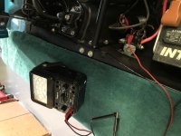
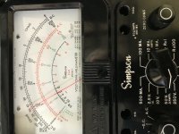
See attached photos: Ign Sw in RUN position, 12V @ Solenoid Brown wire.
(I hate my sideways photos):embarass:

Neil
 

Attachments

  • IMG_0468.JPG
    IMG_0468.JPG
    90.2 KB · Views: 50
  • IMG_0469.jpg
    IMG_0469.jpg
    100.7 KB · Views: 54

robert campbell

Well-known member
Joined
Apr 10, 2007
Messages
4,322
I just installed the Pertronix Ignitor One on the 68 six shooter I just finished. Used the Pertonix 40511 coil as recommended. Pertronix systems DO NOT work well with stock coils, but I have seen some be ok. I always use a Pertronix coil in these installations.

My 68 six shooter is running on the stock ballasted wire and works great!

Rob
 
OP
OP
Mosesatm

Mosesatm

Well-known member
Joined
Jan 18, 2005
Messages
9,178
See attached photos: Ign Sw in RUN position, 12V @ Solenoid Brown wire.
(I hate my sideways photos):embarass:

Neil

Neil,
I think that post is fed from the ignition circuit, and since there’s something wrong with my ignition circuit I can’t use the post as a coil feed.
 

franklinair

Well-known member
Joined
Mar 1, 2007
Messages
4,744
Then it appears the only course is to correct the wiring circuitry.

Neil
 
OP
OP
Mosesatm

Mosesatm

Well-known member
Joined
Jan 18, 2005
Messages
9,178
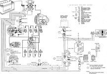
OK you electrical folks, how does the brown wire read 12 volts if the pink wire is 8.5 volts?
 

Attachments

  • E5.pdf
    351.6 KB · Views: 44
  • E5 Diagram.jpg
    E5 Diagram.jpg
    245 KB · Views: 51
Top