• Welcome to the CaliforniaSpecial.com forums! - You are currently viewing the forums as a GUEST. To take advantage of all our site features, please take a moment to join our community! It's fast, simple and absolutely free.

    If you have problems registering or can't log into your account, please contact Admin.

    Please Note: If you are an existing member and your password no longer works, click here to reset it.

1968 Car randomly dies

OP
OP
Batgirl89

Batgirl89

Well-known member
Joined
Nov 14, 2011
Messages
546
Location
Livermore, Ca
I called Pertronix. No help. He said with the relay in everything going through that. Yes the coil gets hot, normal.

Ok so what is frying the Ignition switch? I'm thinking I pull it out and inspect it?
 

CougarCJ

Well-known member
Joined
Jul 17, 2006
Messages
2,216
I called Pertronix. No help. He said with the relay in everything going through that. Yes the coil gets hot, normal.

Ok so what is frying the Ignition switch? I'm thinking I pull it out and inspect it?

Yes, could be.
Also the ignition wiring plug going to the switch is notorious for failing. Look for signs of hot or melted wires at the ignition switch plug.
 
OP
OP
Batgirl89

Batgirl89

Well-known member
Joined
Nov 14, 2011
Messages
546
Location
Livermore, Ca
Yes, could be.
Also the ignition wiring plug going to the switch is notorious for failing. Look for signs of hot or melted wires at the ignition switch plug.
Scott, thank you for the comment. I was looking at the WCCC site last night (because I ordered a proper oil cap for the car) I saw the reproduction plug w/the resistor wire is not recommended by WCCC, a used harness is (but they are out of stock) Can I install the pigtail w/o the resistor wire?

My Theory of whats going on with this car:

(We bought the car with the) Pertronic II system installed on pink resistor wire, starts to fry/damage ignition/pigtail/wires. Car starts dying at random times because wires frying and damage to electrical at ignition switch.

I install relay (Pertronics says this should solve wiring issues) but ignition/pigtail/wires are already damaged and continue to fry because they are now damaged.

So I think my next step is to replace pigtail and switch. I will pull out what is there, do I cut the wires at the old pigtail and just match up the wires on the replacement pig tail except for the pink resistor wire?(I will abandon it)

And then hope that it was the Pertronics that fried it, not something else, because then the new stuff I install will be fried....:scared:
 

Attachments

  • pigtail.png
    pigtail.png
    201.2 KB · Views: 47

rvrtrash

Well-known member
Joined
Apr 25, 2003
Messages
3,665
I hate to get to deep into the weeds, but here's a little tutorial with another of my opinions. On any given circuit, the "load", whether it be light bulb(s), electric motor, whatever, drops the voltage from source, in this case, 12V to ground (0V). The total amount of resistance in a circuit, and the source voltage, determine the amount of current that flows. Current flow is what causes heat. The resistance wire adds resistance to the circuit, which reduces the amount of current. Assuming the wire is sized appropriately, that would mean less heat is generated. The problem with the Pertronix isn't that it heats up the wires, but that the Pertronix doesn't get the full voltage it requires, and has less current flow, for proper functioning. The resistance of the primary coil windings drops part of the 12V and the resistance wire drops the rest. I believe that the reason you see melted wires at the ignition connector is because you have/had a bad connection. Remember I said "assuming ...sized appropriately". If the connectors aren't making good contact, the surface area the current flows through at that spot is smaller, and it generates heat, like a heating coil. The solution is generally to replace both sides of the connection, the switch body and the plug/harness. What you don't want to do is to create a new bad connection and move the problem down the line. Crimp connectors will loosen over time, creating a new bad connection and hot spot. The best way is to correctly solder the wires and insulate with heat shrink tubing, but there are a lot of people that don't know how to solder correctly, and soldering 50 year old wires that have oxidized can be difficult for anyone. The resistance wire is almost impossible to solder, and there's a very good chance of changing the overall resistance by repairing it. That's why a harness replacement is recommended. Hope this makes sense and answers your question.

Steve
 
OP
OP
Batgirl89

Batgirl89

Well-known member
Joined
Nov 14, 2011
Messages
546
Location
Livermore, Ca
I hate to get to deep into the weeds, but here's a little tutorial with another of my opinions. On any given circuit, the "load", whether it be light bulb(s), electric motor, whatever, drops the voltage from source, in this case, 12V to ground (0V). The total amount of resistance in a circuit, and the source voltage, determine the amount of current that flows. Current flow is what causes heat. The resistance wire adds resistance to the circuit, which reduces the amount of current. Assuming the wire is sized appropriately, that would mean less heat is generated. The problem with the Pertronix isn't that it heats up the wires, but that the Pertronix doesn't get the full voltage it requires, and has less current flow, for proper functioning. The resistance of the primary coil windings drops part of the 12V and the resistance wire drops the rest. I believe that the reason you see melted wires at the ignition connector is because you have/had a bad connection. Remember I said "assuming ...sized appropriately". If the connectors aren't making good contact, the surface area the current flows through at that spot is smaller, and it generates heat, like a heating coil. The solution is generally to replace both sides of the connection, the switch body and the plug/harness. What you don't want to do is to create a new bad connection and move the problem down the line. Crimp connectors will loosen over time, creating a new bad connection and hot spot. The best way is to correctly solder the wires and insulate with heat shrink tubing, but there are a lot of people that don't know how to solder correctly, and soldering 50 year old wires that have oxidized can be difficult for anyone. The resistance wire is almost impossible to solder, and there's a very good chance of changing the overall resistance by repairing it. That's why a harness replacement is recommended. Hope this makes sense and answers your question.

Steve
Steve, thank you for the education, I need it with this electrical stuff.
I appreciate your help, Sheryl
 
OP
OP
Batgirl89

Batgirl89

Well-known member
Joined
Nov 14, 2011
Messages
546
Location
Livermore, Ca
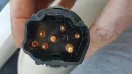
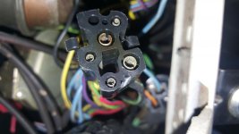
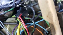
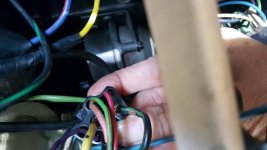
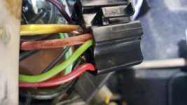
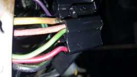
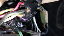
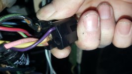
Looks like yellow wire and black/green have been burning others look ok. Under dash wiring all original (no cuts) pristine condition soft/supple. What does the yellow wire run? Black/green is the accessory plug right? (does that run A/C?)
What should I do to fix this?
 

Attachments

  • 20180606_112947_001.jpg
    20180606_112947_001.jpg
    50.8 KB · Views: 62
  • 20180606_113127.jpg
    20180606_113127.jpg
    52.9 KB · Views: 51
  • 20180606_113919.jpg
    20180606_113919.jpg
    64.5 KB · Views: 50
  • 20180606_114033.jpg
    20180606_114033.jpg
    52.5 KB · Views: 56
  • 20180606_114215_001.jpg
    20180606_114215_001.jpg
    54.2 KB · Views: 57
  • 20180606_114222.jpg
    20180606_114222.jpg
    41.9 KB · Views: 61
  • 20180606_114303.jpg
    20180606_114303.jpg
    57.9 KB · Views: 58
  • 20180606_114319.jpg
    20180606_114319.jpg
    57 KB · Views: 63
  • 20180606_113105.jpg
    20180606_113105.jpg
    51 KB · Views: 53
  • 20180606_113005.jpg
    20180606_113005.jpg
    33.8 KB · Views: 57
Last edited:

p51

Well-known member
Joined
Aug 2, 2005
Messages
1,025
Location
NorCal
Looks like yellow wire and black/green have been burning others look ok.
What should I do?

Sheryl

Definitely replace the connector :wink:
What connector is this?

To find the potential cause of the problem I think the next step is to look at the shop manual to determine what function the yellow and black-green (or is that a green-black wire?) wires perform and where they go. The yellow wire in particular looks to be carrying a lot of current.

From a quick and cursory look at the manual pg 19-26 and 19-27 (and not knowing what connector that is) it looks like the black-green (297) wire goes to the "accy only" connector in the ignition switch. This is hooked to 12v during "acc" and "run" and I assume provides power for the radio, etc. The green-black (12) looks like it goes to the headlights (so it probably carries high current when the lights are on). The yellow wire (460) being burnt clearly is carrying high (too much?) current. It appears to be going to the horn/turn-signal circuit (the horn circuit does carry a lot of current when the horn is blown).

What is in the last picture?

James
 
OP
OP
Batgirl89

Batgirl89

Well-known member
Joined
Nov 14, 2011
Messages
546
Location
Livermore, Ca
Sheryl

Definitely replace the connector :wink:
What connector is this?

To find the potential cause of the problem I think the next step is to look at the shop manual to determine what function the yellow and black-green (or is that a green-black wire?) wires perform and where they go. The yellow wire in particular looks to be carrying a lot of current.

From a quick and cursory look at the manual pg 19-26 and 19-27 (and not knowing what connector that is) it looks like the black-green (297) wire goes to the "accy only" connector in the ignition switch. This is hooked to 12v during "acc" and "run" and I assume provides power for the radio, etc. The green-black (12) looks like it goes to the headlights (so it probably carries high current when the lights are on). The yellow wire (460) being burnt clearly is carrying high (too much?) current. It appears to be going to the horn/turn-signal circuit (the horn circuit does carry a lot of current when the horn is blown).

What is in the last picture?

James
James, Thank you for the quick reply! Last pic is just the ignition switch (appears original, autolite) I think I should change it also? I think I should change the headlight switch too (and check wiring & plug) I replace the headlight switch w/a DS148 (the cougar one) in the mustangs

Yes, the yellow wire carrying too much current! Ill read my book, thank you for the pages. Sheryl
 

p51

Well-known member
Joined
Aug 2, 2005
Messages
1,025
Location
NorCal
James, Thank you for the quick reply! Last pic is just the ignition switch (appears original, autolite) I think I should change it also? I think I should change the headlight switch too (and check wiring & plug) I replace the headlight switch w/a DS148 (the cougar one) in the mustangs

Yes, the yellow wire carrying too much current! Ill read my book, thank you for the pages. Sheryl

I just realized that the youtube links I previously had sent you were on how to remove the headlight switch. I meant to send you links on how to remove the ignition switch (which you apparently already know how to do). I've got "headlight switch" on my mind because I'm planning on replacing mine next week... :rolleyes:

Per your question... I think given the problems you've had with ignition, the ignition switch likely should be replaced especially if there is any burn marks, etc. You may(?) want to pull the headlight switch just to check it since it also carries high current. From what I can tell the main high current circuits that pass through the inside of the car are the horn, lights, and the ignition.

IMO, the Shop schematics are fairly hard to follow. I'll spend some more time later today seeing if I can make head or tail of where the black-green and yellow wires go and what exactly they do.
 

Mosesatm

Well-known member
Joined
Jan 18, 2005
Messages
9,178
The yellow wire is the main feed to the switch. If you lose it you lose all power to everything.
 

p51

Well-known member
Joined
Aug 2, 2005
Messages
1,025
Location
NorCal
I finally got it through my thick skull that the connector in the pictures was to the ignition switch :rolleyes:

So, per page 19-37 and 19-36 (as Arlie said) the yellow wire (21) is hooked directly to the battery. Per page 19-26, the black-green wire (297 and 297A) is connected to 12v when the key is in "accessory" or "run" position. So, from this I think we can infer that this wire provides power to just those accessories that one still wants to be using even when the car is not running (eg radio, heater blower, turn signals, etc... any schematic that has 297 or 297A on it).

Now, given the pictures, I think there are two possible ways this could be failing.

(1) The simplest theory of failure is that the insulation of the black-green wire (which really doesn't appear burned) somehow cracked (old age?) allowing for intermittent shorting to ground near the connector. Anytime this would ground out it would cause very high current in the yellow wire (hence the burn) as well as a sag in voltage going out the resistor wire to the coil (or, now, the relay) which would cause the engine to quit. If this is the case, replacing just the connector (and, possibly the ignition switch that is now likely damaged) should do the trick.

(2) The other explanation is that somewhere in the "accessory powered" circuits there is an intermittent short to ground. This short causes high current in both the black-green and yellow wire which led to both wires having cracked insulation. And, as in #1 above, this also leads to engine quitting when the intermittent short occurs. Figuring this out would be more difficult as it would require finding out just which accessory has the intermittent short.

Sheryl, with the idea that #1 is the problem you could just replace the connector/switch and drive it to see if that fixes the problem. If it doesn't or the connector starts to show signs of high current then the short becomes harder to solve.

Aside: none of this explains why the ignitor relay purple wire (which is the control input to the relay) got so hot... that is confusing to me...
 
Last edited:
OP
OP
Batgirl89

Batgirl89

Well-known member
Joined
Nov 14, 2011
Messages
546
Location
Livermore, Ca
I finally got it through my thick skull that the connector in the pictures was to the ignition switch :rolleyes:

So, per page 19-37 and 19-36 (as Arlie said) the yellow wire (21) is hooked directly to the battery. Per page 19-26, the black-green wire (297 and 297A) is connected to 12v when the key is in "accessory" or "run" position. So, from this I think we can infer that this wire provides power to just those accessories that one still wants to be using even when the car is not running (eg radio, heater blower, turn signals, etc... any schematic that has 297 or 297A on it).

Now, given the pictures, I think there are two possible ways this could be failing.

(1) The simplest theory of failure is that the insulation of the black-green wire (which really doesn't appear burned) somehow cracked (old age?) allowing for intermittent shorting to ground near the connector. Anytime this would ground out it would cause very high current in the yellow wire (hence the burn) as well as a sag in voltage going out the resistor wire to the coil (or, now, the relay) which would cause the engine to quit. If this is the case, replacing just the connector (and, possibly the ignition switch that is now likely damaged) should do the trick.

(2) The other explanation is that somewhere in the "accessory powered" circuits there is an intermittent short to ground. This short causes high current in both the black-green and yellow wire which led to both wires having cracked insulation. And, as in #1 above, this also leads to engine quitting when the intermittent short occurs. Figuring this out would be more difficult as it would require finding out just which accessory has the intermittent short.

Sheryl, with the idea that #1 is the problem you could just replace the connector/switch and drive it to see if that fixes the problem. If it doesn't or the connector starts to show signs of high current then the short becomes harder to solve.

Aside: none of this explains why the ignitor relay purple wire (which is the control input to the relay) got so hot... that is confusing to me...

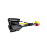
James, Thank you so much for putting so much time into my problem! I have such a hard time trying to follow the schematics! I think you are right, Ill start with the #1 fix and see if that fixes the problem, I will know pretty fast if that heats up after the fix. Now, I just have to figure out the how to replace the pigtail. I wish I could just pull the 2 bad wires out, and put a new connector pin on them and put them back in. Because the pink wire and all the others are in good condition.
And replace the ignition switch. (sorry about throwing you off with the ignition switch picture)
 

p51

Well-known member
Joined
Aug 2, 2005
Messages
1,025
Location
NorCal
James, Thank you so much for putting so much time into my problem! I have such a hard time trying to follow the schematics! I think you are right, Ill start with the #1 fix and see if that fixes the problem, I will know pretty fast if that heats up after the fix. Now, I just have to figure out the how to replace the pigtail. I wish I could just pull the 2 bad wires out, and put a new connector pin on them and put them back in. Because the pink wire and all the others are in good condition.
And replace the ignition switch. (sorry about throwing you off with the ignition switch picture)

In some cases you can remove wires/pins from connectors - those that have internal release tabs. I have never done it but have seen it done (on Auto RestoMod on Youtube). Here is some links that might help...
https://www.youtube.com/watch?v=znP_uZCak7M

A tool for releasing the tabs...
https://www.amazon.com/Lisle-56500-Terminal-Tool/dp/B0009OR906
 
OP
OP
Batgirl89

Batgirl89

Well-known member
Joined
Nov 14, 2011
Messages
546
Location
Livermore, Ca

franklinair

Well-known member
Joined
Mar 1, 2007
Messages
4,744
Here's my 2 cents worth on the 'fix'. (Get rid of the extraneous component(s) you've already installed.)
1.) Replace the Ignition Switch due to potential overheated sockets.
2.) Replace the Ignition Switch Pigtail due to overheated wire/insulation.
3.)Splice the new pigtail into the existing under dash harness- (ALL wires, including the Pink wire)
4.) Use crimped splices. (They will not fail/corrode if properly crimped.) Airlines have been using them for decades with no problem.

Now for my modification for 12V to the Coil + terminal at ALL times (Starting or Running):

Locate the 2 connectors at the firewall, adjacent to the left valve cover.
The square one will have a Black/Red wire (#140)
The skinny connector will have a Red/Green wire (#16B).
Install a Jumper wire between the two.- I use a 18 gauge wire with Black insulation so as not to be too visible. I strip the insulation about 3/8" on both ends and insert each end into the respective receptacles. Its a tight fit, but goes in OK.
This configuration will allow 12V to the Coil when Starting, and 12V to the Coil when running, with no ill side affects. Due to 12V being applied on both ends of the Pink wire, there is no current flow when in the Run position. It will last forever.
The Pertronix installation should be done as per instructions, using their higher voltage Coil.
All will be well.

Neil
 
OP
OP
Batgirl89

Batgirl89

Well-known member
Joined
Nov 14, 2011
Messages
546
Location
Livermore, Ca
Here's my 2 cents worth on the 'fix'. (Get rid of the extraneous component(s) you've already installed.)
1.) Replace the Ignition Switch due to potential overheated sockets.
2.) Replace the Ignition Switch Pigtail due to overheated wire/insulation.
3.)Splice the new pigtail into the existing under dash harness- (ALL wires, including the Pink wire)
4.) Use crimped splices. (They will not fail/corrode if properly crimped.) Airlines have been using them for decades with no problem.

Now for my modification for 12V to the Coil + terminal at ALL times (Starting or Running):

Locate the 2 connectors at the firewall, adjacent to the left valve cover.
The square one will have a Black/Red wire (#140)
The skinny connector will have a Red/Green wire (#16B).
Install a Jumper wire between the two.- I use a 18 gauge wire with Black insulation so as not to be too visible. I strip the insulation about 3/8" on both ends and insert each end into the respective receptacles. Its a tight fit, but goes in OK.
This configuration will allow 12V to the Coil when Starting, and 12V to the Coil when running, with no ill side affects. Due to 12V being applied on both ends of the Pink wire, there is no current flow when in the Run position. It will last forever.
The Pertronix installation should be done as per instructions, using their higher voltage Coil.
All will be well.

Neil

Neil, Thank you!!
Sheryl
 

robert campbell

Well-known member
Joined
Apr 10, 2007
Messages
4,322
Hope this is all an electrical gremlin. My 2 cents might be over heat, poor timing, and carb adjustment. We will see.

Rob
 
OP
OP
Batgirl89

Batgirl89

Well-known member
Joined
Nov 14, 2011
Messages
546
Location
Livermore, Ca
Hope this is all an electrical gremlin. My 2 cents might be over heat, poor timing, and carb adjustment. We will see.

Rob

I agree. John thinks timing is off.....
why aren't you closer Dr. !!!!!! so you could tune this sucker after I get the plugs and switches replaced
 
Top